
What is a Reflected Ceiling Plan (RCP)? Ultimate guide
This guide breaks down what an RCP needs to include, how to read it, and how to document existing conditions the right way. You’ll learn how each system interacts and how to avoid the common mistakes that lead to rework, delays, and inspection issues.
Definition of RCP
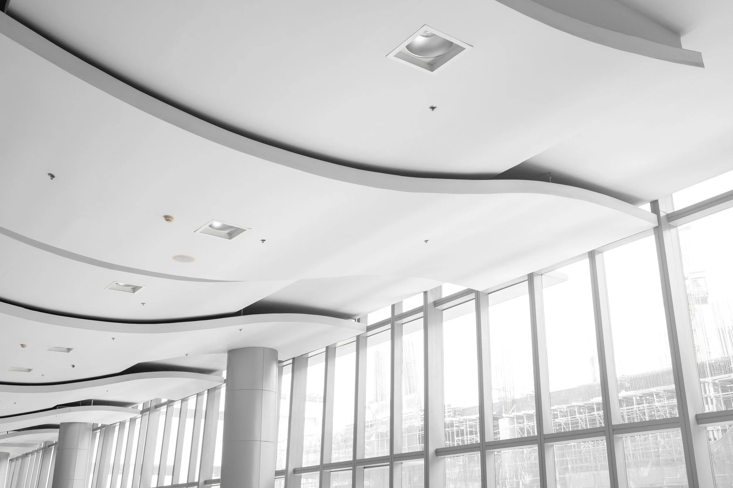
A reflected ceiling plan (RCP) is an architectural drawing that shows the ceiling as if a large mirror were placed flat on the floor. Imagine looking down at that mirror and seeing the entire ceiling reflected back at you, helping you visualize the layout of all ceiling-mounted elements. This “reflected” view keeps the same orientation as the floor plan, which makes it easy to compare both drawings and coordinate every ceiling-mounted element with the layout below.
By providing exact placement and height data for every element, the RCP serves as the project’s primary coordination tool and often supports coordination with the project’s BIM model. It shows how electrical, HVAC, and structural components work together, helping the team identify and avoid spatial conflicts before construction begins. When the RCP is accurate, every trade follows one unified and conflict-free layout.
Beyond design clarity, the plan carries legal and financial importance. It forms an essential part of the documentation used for permitting.
What’s Included in a Ceiling Plan
Ceiling Height Information
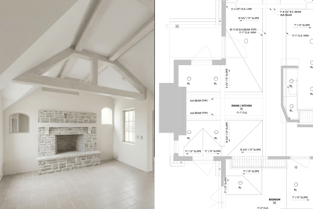
Height annotations on a Reflected Ceiling Plan define the exact vertical dimensions of a space. In U.S. construction documents, these heights are almost always referenced to CLG (Ceiling Height). However, professional RCPs, especially those involving exposed structures or existing building renovations, require more specific technical callouts to ensure accuracy:
CLG LOW - The lowest height on a sloped ceiling above the floor
CLG HIGH - The highest point on a sloped ceiling above the floor
B.O. BEAM (Bottom of Beam): Indicates the elevation from the floor to the lowest point of a structural beam. This is a critical parameter for coordinating tall equipment and ensuring minimum clear ceiling heights required by code.
Additional annotations may include the ridge location and size, beams, or exposed rafters.
When an architect requests to illustrate more information, additional symbols and annotations should be added, such as a vent, molding, smoke detector, etc.
Graphic Representation and Tagging
On an RCP, heights are displayed as numeric callouts placed directly within the corresponding zones. Every area with a distinct elevation must have its own height tag. For instance, a label such as 13'-7" B.O. BEAM clearly establishes a boundary that mechanical runs, conduits, or interior elements cannot exceed.
In cases involving sloped ceilings, the plan must include the pitch or slope (e.g., 1/8" / 12"). This allows the team to calculate elevation changes accurately across the room, ensuring proper wall intersections and fixture mounting.
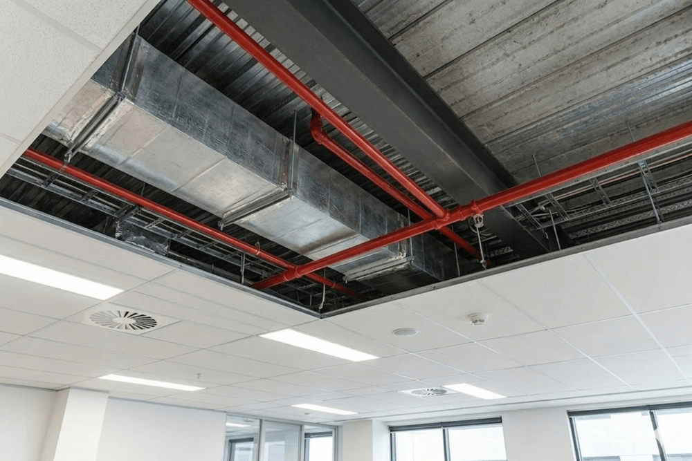
Plenum Space and System Coordination
Precise height data for beams and joists serves as the primary guide for installing systems within the Plenum Space. Vertical coordination allows the team to:
Route HVAC ductwork and VAV boxes without conflicting with primary structural members.
Determine the feasibility of recessed lighting fixtures based on the available clearance.
Ensure unobstructed access to critical utility components, such as Water Meters or shut-off valves.

Coordination With HVAC, Structure, and Fire Protection
The RCP coordinates device locations with:
HVAC diffusers and returns
Fire sprinklers
Structural beams
Plenum depth limitations
Access panels for mechanical equipment
Structural and Material Elements
Structural and material elements define the physical conditions that shape the ceiling and control how all systems must be coordinated. These components show the real limits of the space, what cannot move, what can be modified, and how much plenum depth is available for HVAC, electrical, and fire-protection routing.
| Category | What It Includes | Why It Matters |
|---|---|---|
| Structural Elements |
|
|
| Materials |
|
|
| Architectural Features |
|
|
Mechanical, Electrical, and Plumbing (MEP) Features
MEP features give the ceiling plan its technical backbone. They document all devices at the finished plane and show how air, life-safety, and digital systems work together within the design.
| Category | What Appears on the RCP | Why It Matters |
|---|---|---|
| Air Distribution (HVAC) |
|
|
| Life Safety & Security Devices |
|
|
| Infrastructure & Communications (Low-Voltage) |
|
|
| Access & Maintenance |
|
|
| Plumbing Elements (Only When They Affect the Ceiling) |
|
Plumbing appears only when it changes the ceiling plane. |
Technical Annotations and Dimensions
They tell the builder exactly where each element goes, how it aligns, and at what height it must be installed. Dimensions lock in centerlines and offsets so that lighting, HVAC, and fire-safety devices don’t drift during construction. Height callouts show where the ceiling stays level and where it changes because of soffits, drops, or slopes.
-
Dimensions
Measurements that locate lights, diffusers, sprinklers, and other devices. They lock the final centerlines and keep the layout aligned with walls, grids, and architectural features.
-
Centerlines
Thin solid reference lines showing symmetry or alignment points. They help the installer keep devices straight, balanced, and centered within ACT tiles or along architectural axes.
-
Offset Notes
Short annotations showing how far a fixture sits from a wall, column, soffit, or grid line. They’re used when the device cannot rely on the grid module for exact placement.
-
Ceiling Height Callouts
Tags like CLG and B.O. BEAM identify the finished height. These callouts define the room’s vertical plane and mark level areas, transitions, and height changes.
-
Break Lines
Jagged lines show that the drawing continues off the page. Break lines keep the sheet readable and signal that dimensions or details continue on another view.
-
Material Change Indicators
Notes or boundary lines showing where the ceiling switches between ACT, GWB, wood, metal, or other materials. Different materials have different mounting needs. Installers must know where transitions occur to avoid misalignment or gaps.
-
Slopes and Angles
Slope indicators show tilted planes that influence fixture alignment, trim selection, and device orientation.
-
Soffit and Bulkhead Notes
Annotations marking lowered sections, bulkheads, or drops. These elements hide ductwork, structure, or lighting conditions.
-
Section Markers
Callouts showing where a section or detail cut occurs. They direct the reader to enlarged drawings that show tricky areas: soffits, vaulted ceilings, transitions, or tight plenum conditions.
-
Alignment Notes
Short text directing installers to “align to grid,” “center on opening,” or “align to wall.”
-
Room Labels
Names or numbers showing which space the reflected ceiling plan belongs to. Room names tie the layout to the furniture plan, finish plan, and MEP sheets.
-
Tags for Devices
Tags connect symbols on the RCP to schedules. Without tags, the contractor doesn’t know which device type to install.
The Legend and Tags
The legend and tags turn the reflected ceiling plan into a clear communication tool instead of a collection of unexplained symbols of a messy workflow. They define what each symbol, tag, and abbreviation means and connect the drawing to schedules and specifications.
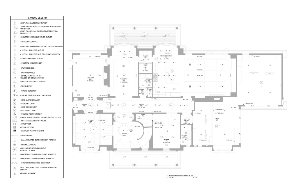
Symbol Legend
A graphic list of all symbols used on the plan.
- lighting fixtures
- HVAC diffusers and grilles
- sprinkler heads
- smoke detectors
- speakers and AV devices
- Wi-Fi access points
- access panels
Abbreviations and Acronyms
Shortened terms are used throughout the plan.
- CLG – Ceiling
- SD – Smoke Detector
- ACT – Acoustical Ceiling Tile
- FA – Fire Alarm
Tags
Numbered or lettered notes are tied to specific conditions on the plan. Instead of repeating long text, the plan uses one note and references it where needed.
Material and System Callouts
Legend entries that explain ceiling types and system boundaries. These callouts tell the crew what system belongs in each zone.
Coordination and General Notes
Short statements grouped near the legend.
- “Align fixtures to ceiling grid unless noted otherwise.”
- “Coordinate sprinkler locations with lighting.”
- “Verify field conditions before installation.”
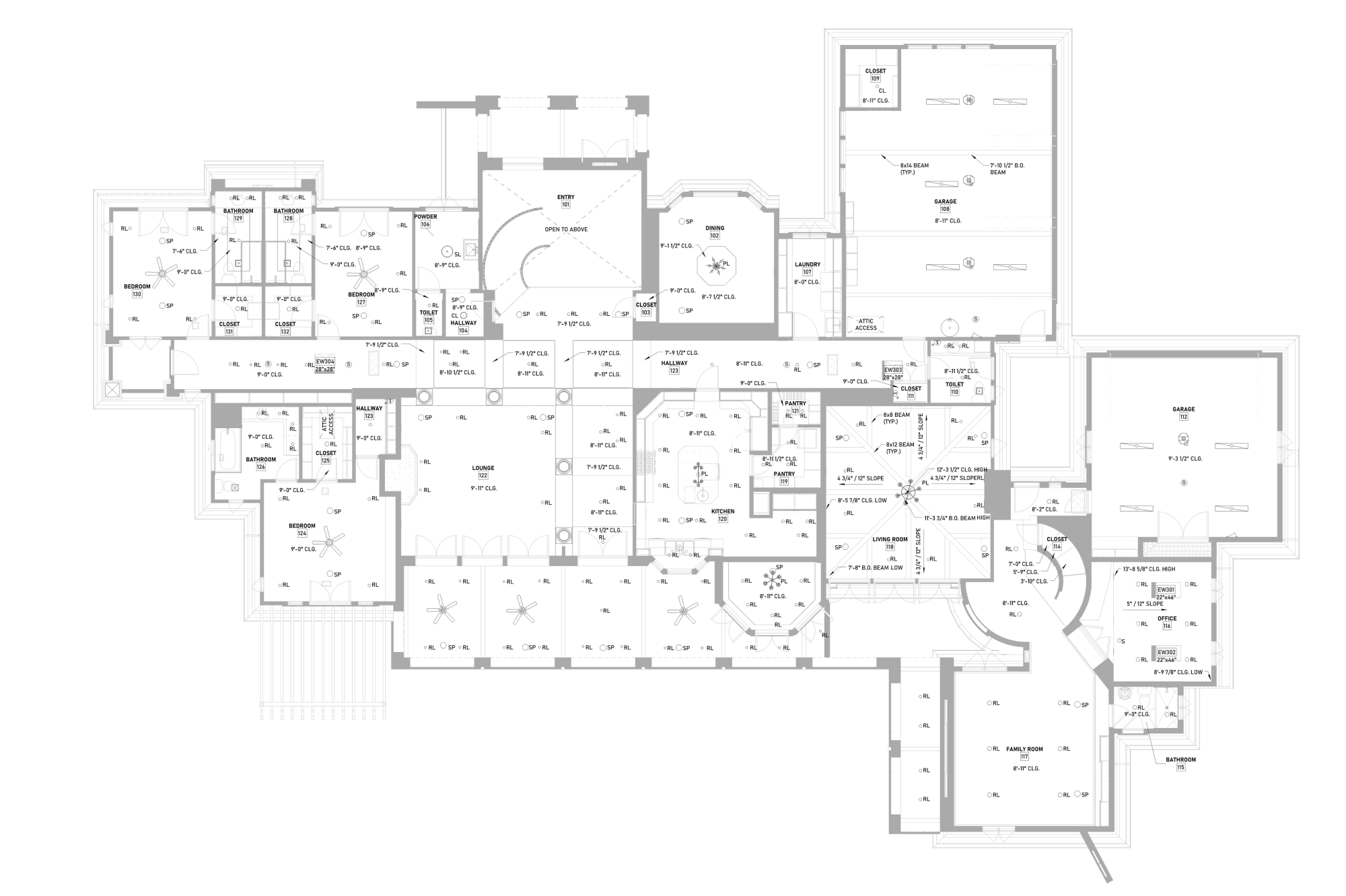
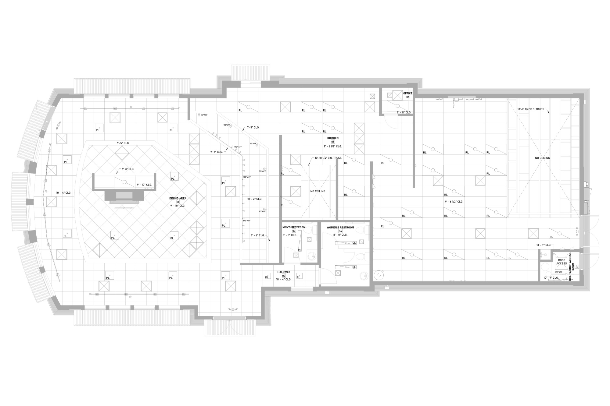
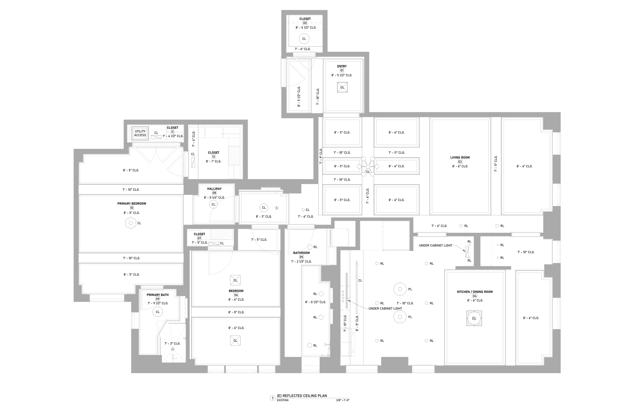
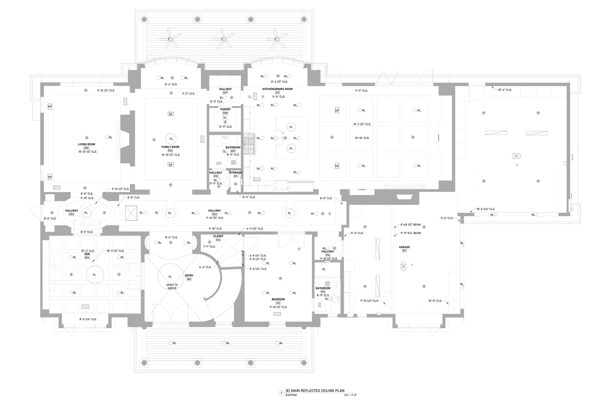
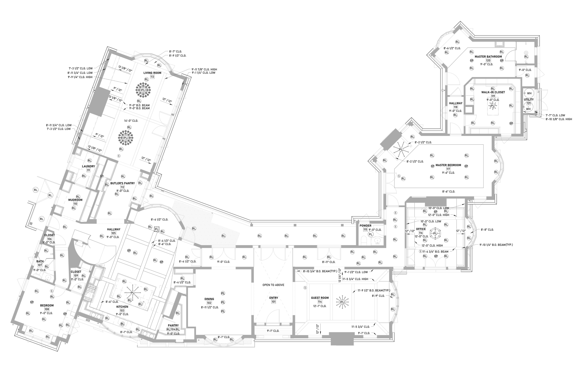
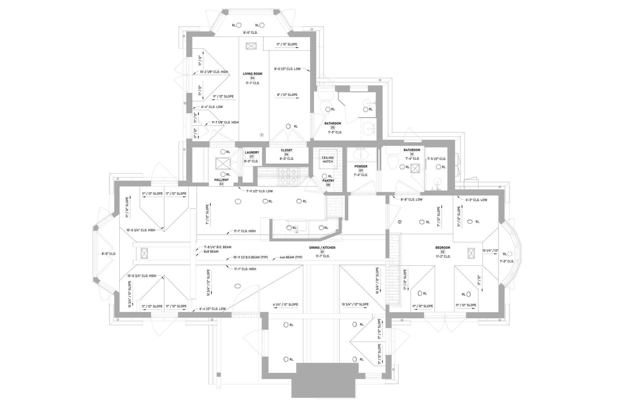
Example of a Reflected Ceiling Plan
Why are Ceiling Plans so Important?
-
Reveal existing conditions and hidden constraints
As-built ceiling plans show what’s really there: beam locations, ceiling heights, soffits, and plenum limits. That information matters when you plan a renovation or upgrade. It shows what you can change and what you should work around.
-
Ensure proper lighting, comfort, and performance
A good plan balances illumination, air distribution, and height, directly affecting brightness, airflow, and daily comfort.
-
Coordinate lighting, HVAC, fire protection, and technology
Ceiling plans coordinate multiple building systems into one clear drawing. They show how lighting, HVAC, sprinklers, and other ceiling elements are arranged, helping prevent conflicts and ensuring everything fits and functions properly.
-
Provide clear instructions for builders and installers
Contractors rely on RCPs to know exact locations, heights, and alignments. Clear drawings reduce questions, speed up installation, and keep work consistent across trades.
-
Support permits, inspections, and code compliance
Building departments review ceiling plans to check fire safety, lighting controls, and life-safety systems. Inspectors use them to verify spacing and placement in the field. A complete plan helps projects pass reviews without delays.
-
Prevent costly mistakes and rework
Fixing conflicts after installation costs time and money. Early planning prevents issues before wires, ducts, and fixtures go in, saving budget and protecting the schedule.
How to Check an Existing Reflected Ceiling Plan
Room Geometry Alignment
Verify that ceiling elements align with the floor plan, including walls, columns, shafts, and room boundaries.
Mistakes: Ceiling fixtures not centered in rooms, misaligned grids, or elements shifted from walls and structural lines.
Heights
Check that every ceiling zone has clear height annotations such as CLG, FCL, AFF, B.O. BEAM, CLG LOW, or CLG HIGH.
Mistakes: Missing height tags, inconsistent heights between zones, or heights that conflict with beams and structural elements.
Type Boundaries
Confirm that different ceiling materials (ACT, GWB, metal panels, exposed structure) are clearly marked and separated.
Mistakes: Unclear material transitions, missing boundary lines, or ceiling types not labeled.
Structural Elements
Verify that beams, joists, girders, or the underside of the slab are accurately shown and dimensioned.
Mistakes: Structural elements are missing from the plan, or fixtures are placed where the structure would block installation.
Lighting Fixture Layout
Check fixture spacing, alignment with ceiling grids, and proper placement relative to room geometry.
Mistakes: Uneven spacing, fixtures not aligned to the grid or centerlines, or lights too close to walls or architectural features.
HVAC Devices
Verify locations of supply diffusers, return grilles, and exhaust vents and their spacing relative to lighting and sprinklers.
Mistakes: Diffusers too close to lights or sprinklers, airflow blowing directly across smoke detectors, or a poor distribution layout.
Fire Protection Devices
Confirm that sprinkler heads follow spacing requirements and maintain clearance from lights and diffusers.
Mistakes: Sprinklers located too close to other devices or with irregular spacing may fail code inspection.
Life Safety Devices
Ensure smoke detectors, fire alarm strobes, exit signs, and cameras are shown and correctly tagged.
Mistakes: Missing devices, unclear symbols, or inconsistent tagging could cause installation errors.
Sensors and Low-Voltage Devices
Verify placement of occupancy sensors, daylight sensors, Wi-Fi access points, speakers, and AV equipment.
Mistakes: Missing low-voltage devices or placement that interferes with lighting or structure.
Architectural Ceiling Features
Check for soffits, bulkheads, coves, coffers, and sloped or vaulted ceilings.
Mistakes: Vertical transitions are not documented, resulting in unexpected conflicts during installation.
Dimensions and Centerlines
Verify that centerlines, offsets, and dimensions clearly define fixture and device locations.
Mistakes: Missing measurements that allow elements to “drift” during construction.
Device Tags and Schedules
Confirm that each symbol on the plan has a tag linked to a schedule or legend.
Mistakes: Untagged devices or inconsistent naming between the plan and schedules.
Legend and Symbol Clarity
Ensure the drawing includes a complete legend explaining symbols, abbreviations, and notes.
Mistakes: Confusing or missing legend leading to different interpretations by trades.
Damage and Defects
Check annotations for existing issues such as water stains, cracked gypsum, or sagging tiles.
Mistakes: Damage was not documented, which can lead to hidden renovation costs.
Documentation Completeness
Confirm that all visible ceiling-mounted elements appear on the drawing and that notes are clear and consistent.
Mistakes: Missing fixtures, inconsistent notes, or incomplete labeling of systems.
Final Coordination Review
Cross-check the RCP with floor plans, sections, and field measurements before approval.
Mistakes: Conflicts between drawings, incorrect measurements, or elements that do not match site conditions.
In practice, the plan of the ceiling design is one of the most critical coordination drawings in a project. When it is accurate and complete, it eliminates guesswork in the field, protects the construction schedule, and ensures every ceiling system fits and performs as intended.


